1) Before you measure: confirm the architecture and end interfaces
Different architectures use different reference points. Before you put a tape measure on anything, capture:- Which shaft: front / rear / intermediate; 1-piece vs 2-piece (center support).
- End interfaces: flange, yoke, slip yoke/spline, or CV interface.
- Condition notes: missing weights, dents, bent tube, or non-original modifications (these can affect quote acceptance).
Scope boundary: This page focuses on measuring length for quoting. If you need a full component encyclopedia, use Parts on a drive shaft. If you need installation steps, use How to replace a drive shaft.
2) Choose the correct measurement method
Below are the most common quoting methods. The correct one depends on your end interfaces and whether the shaft includes a slip section. Tip: click a header to sort
| Method name | Measure from → to | Best for | Buyer note (avoid mis-quotes) |
|---|---|---|---|
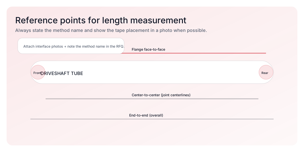
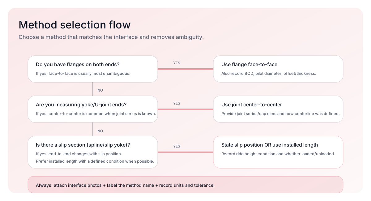
| Flange-to-flange (face-to-face) | Front flange mating face → rear flange mating face | Flange-ended shafts (common on many assemblies) | Confirm bolt circle/pilot/offset in addition to face-to-face length. |
| Center-to-center | Centerline of front joint → centerline of rear joint | Yoke/U-joint-ended shafts when joint series is known | State how “center” was identified and include joint series/cap dims. |
| End-to-end (overall) | Overall maximum length end point → end point | When required by internal records or legacy drawings | Risky if slip travel exists; always specify slip position during measurement. |
| Installed length (in-vehicle) | Installed position reference points under normal ride height | Programs where suspension/axle position matters | State ride height condition and whether suspension is loaded/unloaded. |
3) Step-by-step: how to measure (field workflow)
This is a field-friendly workflow designed to reduce RFQ back-and-forth. Use it whether you are measuring a removed shaft or capturing installed length in the vehicle/equipment.Step A — Take interface photos first
- Take one photo of the front interface (flange/yoke/CV/spline) straight-on.
- Take one photo of the rear interface straight-on.
- If applicable, take a photo of the center support / carrier bearing and bracket geometry (2-piece shafts).
Step B — Choose and label the method
Write the method name in your notes and on the photo (or in the file name). Example: “flange-face to flange-face”.Step C — Measure with repeatability
- Use a rigid tape or measuring bar when possible (flexible tapes can sag).
- Measure twice and record both readings. If the two values differ, re-check the reference points.
- If there is a slip section, record the slip position used during measurement (e.g., fully seated, mid-travel).
Step D — Record what suppliers actually need to quote
Length alone is not enough. Always pair length with interface geometry and joint family.Ready to quote? After you fill the measurement sheet below, submit your inquiry on /drive-shaft/.
4) Drive Shaft Measurement Checklist
Use this checklist to prepare the key details needed for drive shaft matching. Clear measurements, interface photos, and vehicle information can help reduce quotation errors and fitment mistakes before ordering.DRIVE SHAFT MEASUREMENT CHECKLIST A) Vehicle and shaft identification - Vehicle / application: - Drivetrain layout: RWD / 4WD / AWD - Shaft position: front / rear / intermediate - Shaft design: 1-piece / 2-piece - Center support or carrier bearing details, if applicable: B) Length measurement - Measurement method: flange-face to flange-face / center-to-center / end-to-end / installed length - Measured length: - Units: mm / in - Measurement condition: installed or removed; loaded or unloaded ride height - Second measurement reading, if available: C) End interfaces - Front interface type: flange / yoke / CV / spline-slip - Front interface details: bolt circle, pilot diameter, offset, yoke series, or spline count - Rear interface type: flange / yoke / CV / spline-slip - Rear interface details: D) Joint and connection details - U-joint series, cap diameter and span, or CV joint model/family: - Service type: serviceable / sealed E) Tube and support details - Tube condition: dents, bends, missing balance weights, or visible damage - Tube outside diameter and wall thickness, if known: - Center support or carrier bearing size and bracket details, if applicable: F) Order details - Quantity: - Target delivery date: - Delivery location: Photo checklist: [ ] Front interface photo, taken straight-on [ ] Rear interface photo, taken straight-on [ ] Full shaft photo [ ] Photo of any tube damage or missing balance weights [ ] Photo showing the tape measure and reference points
If you only have an OE part number: include the OE number, but still provide front and rear interface photos and confirm which length measurement method was used.
5) Common mistakes that cause mis-quotes (and how to avoid them)
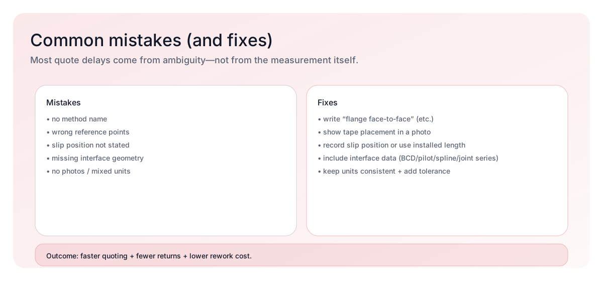
- Sending a length without the method: “48 inches” is meaningless unless you state face-to-face, center-to-center, etc.
- Ignoring slip position: end-to-end numbers change if the slip is compressed vs extended.
- Missing interface geometry: length can be correct while the flange/yoke/CV interface is wrong.
- No photos: suppliers will ask follow-ups; your quote cycle time increases.
- Mixing units: state mm vs inches and keep the sheet consistent.
6) FAQ
How do you measure driveshaft length?
Pick a method that matches your interfaces (commonly flange face-to-face, joint center-to-center, or overall end-to-end), measure between those reference points, and record the method name alongside the number. Include photos so suppliers can validate the reference points. [S1][S2]What is “flange-to-flange” measurement?
It’s the distance from the mating face of the front flange to the mating face of the rear flange. It’s common for flange-ended shafts, but you still need flange geometry (bolt circle, pilot, offset) for a complete quote.What does “center-to-center” mean on a driveshaft?
It typically means the distance between the centerlines of the joint interfaces (often U-joint centerlines). State how you identified the centerline and provide the joint series/cap dimensions.Does slip yoke position affect the length measurement?
Yes. If the shaft uses a slip section, the overall end-to-end length changes when the slip is compressed vs extended. Always state the slip position or use a measurement method that removes ambiguity for your application.What should I send to get a fast quote?
Send the completed measurement sheet plus photos of both end interfaces and the measurement setup. Then submit your RFQ on our drive shaft product page.7) How This Guide Was Prepared
This guide explains common ways to measure drive shaft length, including flange-to-flange, center-to-center, end-to-end, and installed-length methods. It is written for readers who need to confirm the correct measurement method, reference points, and supporting photos before ordering a replacement drive shaft. The measurement methods are organized around practical part-matching needs. Because the same length number can mean different things depending on where it was measured, this guide emphasizes clear reference points, end-interface photos, and repeatable measurement steps. The ±1–2 mm note is a practical field-measurement repeatability guideline, not a universal tolerance rule. Actual requirements can vary by vehicle, shaft design, supplier instructions, and OEM measurement conventions. Measurement terminology and driveline reference-point conventions are based on the service and manufacturer references listed below. Always confirm the measurement method against the vehicle’s service information, drawing, or supplier requirements before ordering.8) Sources
Sources are cited inline using bracket codes such as [S1] and [S2].
- [S1] Dana / Spicer — driveline service resources and terminology used for measurement reference point conventions.
- [S2] NHTSA-hosted service and training PDFs — driveline setup and vibration documentation that emphasizes correctly defined reference points and verification.