What’s Front vs Rear Drive Shaft Different for Sourcing
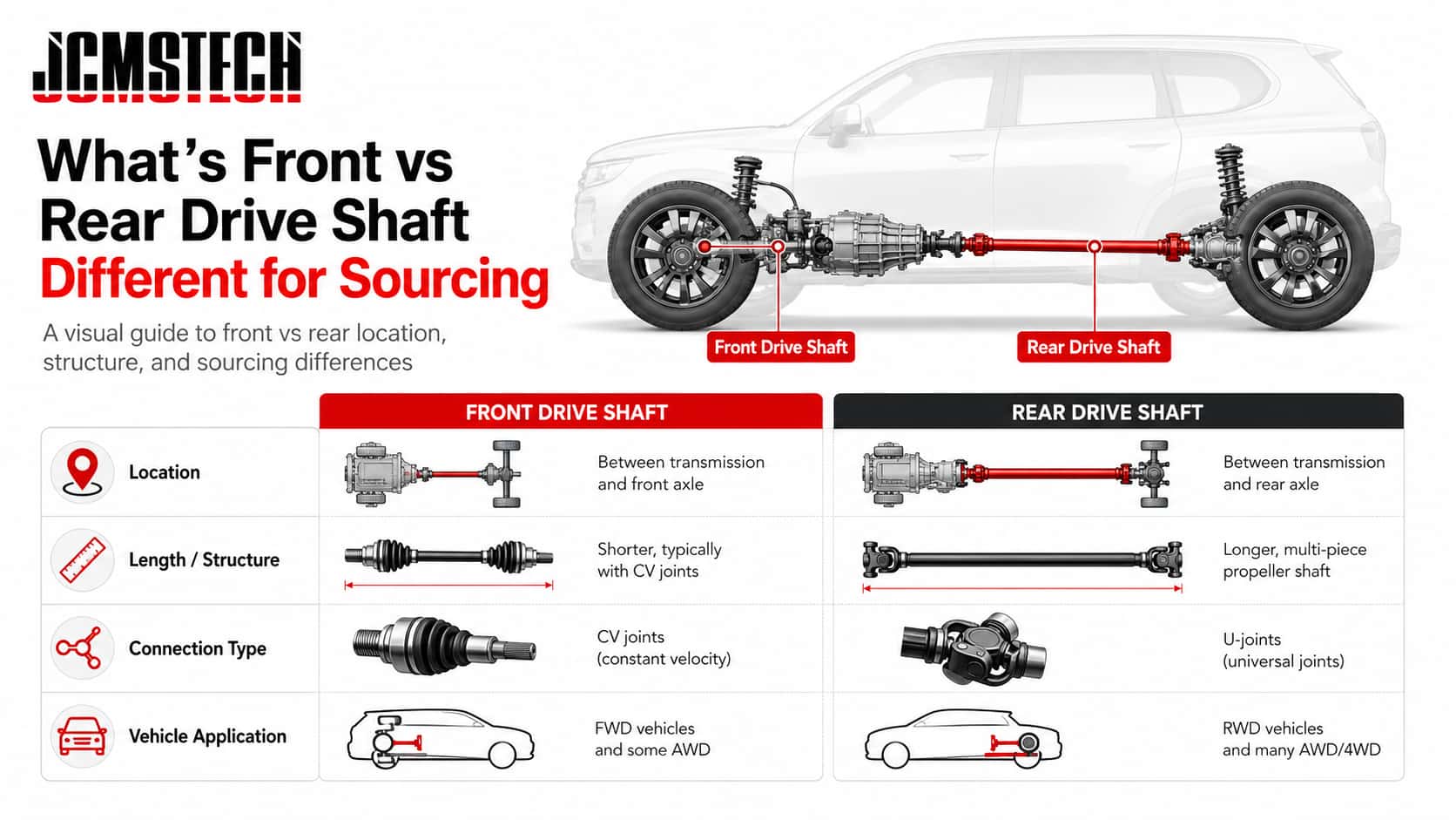
“Front drive shaft” can mean different things depending on the platform. In this hub, we use drive shaft to mean the propeller shaft / driveshaft assembly that transmits torque between drivetrain components—not a CV axle/halfshaft. If your team needs definitions and types, use What is a drive shaft?
One-sentence answer:
- 3 positions
Common “which shaft” options in programs: front, rear, and intermediate (especially on AWD/2-piece layouts).
Scope: sourcing terminology; not a vehicle-spec rule. - 2 ends
Two interfaces always: a supplier must match the front end and the rear end interface—photos of both ends are the minimum evidence set.
Scope: RFQ evidence standard. - 8 fields
8 details to confirm before ordering: shaft position, drivetrain layout, length measurement method, front interface, rear interface, joint family, slip details, and any required quality or fitment checks.
Use this as: a practical part-matching checklist based on common measurement and order information. [S2][S3]
Where the front and rear drive shafts are located
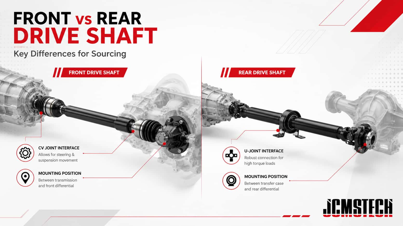
For many 4WD/AWD systems, the drivetrain may include:- Front drive shaft: commonly connects the transfer case / PTU to the front differential.
- Rear drive shaft: commonly connects the transmission/transfer case output to the rear differential.
- Intermediate shaft when present: a section used to manage packaging, length, or support/bearing requirements.
What typically changes between front vs rear: interfaces and constraints
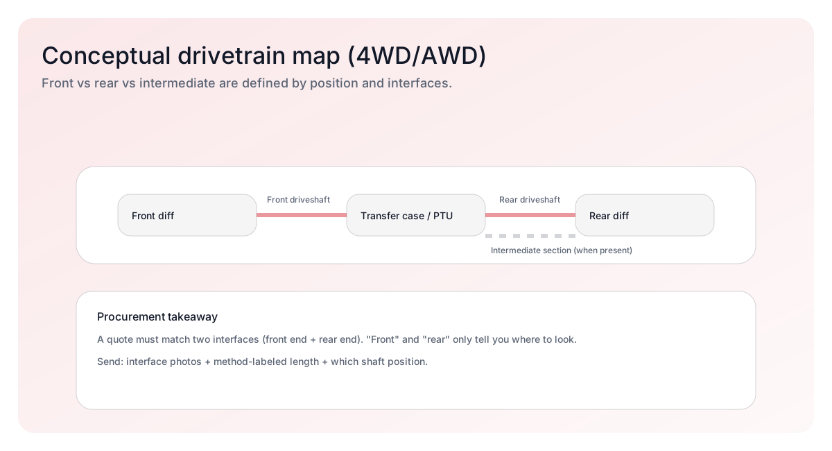
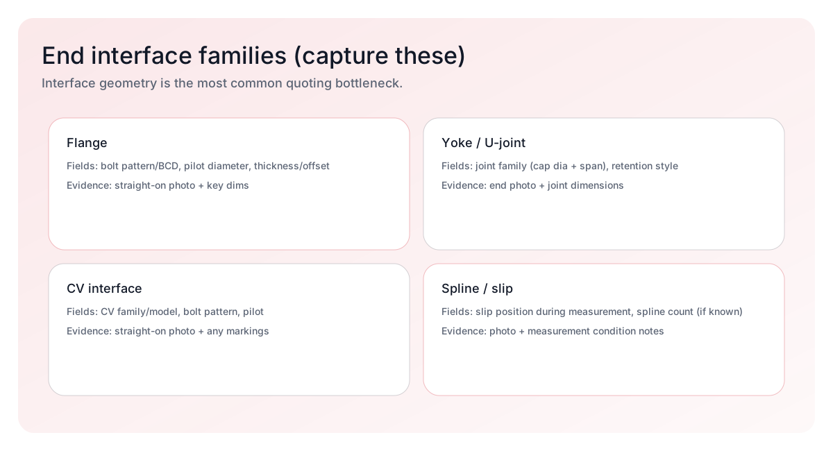
For part matching, “front vs rear” is less about the name and more about mating interfaces, shaft location, and packaging constraints. Suppliers usually need these details to avoid wrong-part matching:- Front-end interface type and geometry, such as flange, yoke, CV, or spline.
- Rear-end interface type and geometry.
- Whether there is a slip/spline section and how it was positioned during measurement.
- Any constraints such as corrosion exposure, clearance limits, vibration concerns, or verification requirements.
Front vs rear vs intermediate: position comparison table
This is a general comparison, not a vehicle-specific rulebook. Use it to decide which details should be confirmed before asking a supplier to check the correct drive shaft.| Shaft position | Common connects | Interfaces to confirm | Common matching risks | What to prepare |
|---|---|---|---|---|
| Front drive shaft | Transfer case / PTU → front differential | Front interface + rear interface + slip position if present | Wrong flange pilot/bolt pattern; confusion with CV axle; missing slip details | State “front propshaft” clearly; attach both end photos; label the length measurement method. |
| Rear drive shaft | Transmission/transfer case output → rear differential | Interfaces on both ends; note if a 2-piece support exists | 2-piece support or bracket mismatch; unclear length reference points; vibration-related disputes | Confirm 1-piece vs 2-piece design; provide support bracket geometry; describe any verification requirements. |
| Intermediate shaft when present | Between gearbox/PTU/transfer case sections or support points | Interfaces + support/bearing details | Wrong support or bearing specification; incorrect offset alignment; packaging constraints | Provide photos of support/bearing and mounting points; confirm offsets and location. |
Information suppliers need for front vs. rear drive shafts
To reduce clarification requests and part-matching mistakes, prepare these details before asking a supplier to check the correct shaft.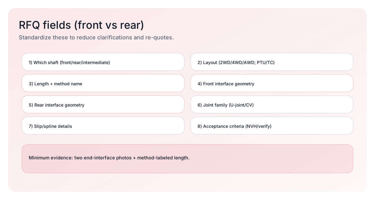
| Detail | Why it matters | What to send | Related guide |
|---|---|---|---|
| Which shaft front / rear / intermediate | Clarifies location and reduces wrong-part substitution. | Write it explicitly and add a photo showing installation location if possible. | What is a drive shaft? |
| Drivetrain layout 2WD / 4WD / AWD; transfer case / PTU | Determines which components the shaft mates to. | Layout notes and any known platform identifiers. | Function and common types |
| Length + method name | “Length” is ambiguous without reference points. | State method, such as face-to-face or center-to-center, plus measurement condition. | Measure length |
| Front interface type and geometry | One of the most common causes of wrong-part matching. | Front end photo + key dimensions, such as pilot/bolt pattern or yoke/joint family. | Parts names |
| Rear interface type and geometry | Must match the mating component. | Rear end photo + key dimensions. | Parts names |
| Joint family U-joint / CV family | Drives end compatibility and service parts. | U-joint cap/spread or known joint series; CV family if applicable. | Parts names |
| Slip / spline details | Changes effective length and fitment. | Spline count if known + slip position used during measurement. | Measurement guide |
| Fitment and verification requirements | Helps reduce rework and unclear acceptance expectations. | Describe verification condition and any vibration, clearance, or fitment requirements. | Replacement overview |
Related drive shaft guides
Use this guide for: understanding front, rear, and intermediate driveshaft differences, where each shaft is located, and which part-matching details can change by position. For related topics: use the guides below for definitions, component names, symptoms, measurement steps, replacement workflow, cost planning, and product inquiries.- Definitions and common types → What is a drive shaft?
- Parts and terminology → Parts on a drive shaft
- Symptoms and failure signs → Signs of a bad drive shaft
- Measurement method → How to measure drive shaft length
- Replacement workflow → How to replace a drive shaft
- Cost planning → Replacement cost
- Product options and inquiry → Drive shaft products
FAQ
What is a front drive shaft?
In many 4WD/AWD drivetrains, the front drive shaft, also called a front propshaft, transmits torque from a transfer case or PTU to the front differential. Some consumer contexts use the term for a CV axle; this guide focuses on propshaft assemblies. [S1]What is the difference between a front and rear driveshaft?
The main differences are the location in the drivetrain and the interfaces that must match on each end. Always state which shaft you mean, such as front, rear, or intermediate, and provide photos of both end interfaces.Do 2WD vehicles have a front drive shaft?
Many 2WD platforms do not use a front propshaft to a front differential. Always confirm the drivetrain layout, such as 2WD, 4WD, or AWD, before asking a supplier to check the correct shaft.What measurements do I need for a front or rear driveshaft?
At minimum, identify which shaft, provide photos of both end interfaces, and state the length with the measurement method name. Use how to measure drive shaft length to prepare consistent measurements and part details. [S2][S3]Where can I request product help?
Share your vehicle details, shaft position, photos, and measurements through our drive shaft product page.How this guide was reviewed
Purpose: This guide helps readers understand front drive shaft and front vs. rear drive shaft differences, including location, drivetrain layout, end interfaces, and the details that should be confirmed before ordering a replacement assembly. How this guide was prepared: The content is organized around practical part-matching questions: where the shaft is located, whether the vehicle uses FWD, RWD, AWD, or 4WD, which end interfaces are used, and which photos, measurements, or part numbers may help confirm the correct drive shaft. The “3 positions” and “8 details” are practical checklists for comparing vehicle details, dimensions, and interface information. Limitations: Actual drive shaft architecture varies by vehicle maker, model, drivetrain, and platform. Always confirm the required part with vehicle-specific information, OE number where available, photos, measurements, and supplier confirmation before ordering.Sources
Sources are cited inline using bracket codes like [S1].
- [S1] Dana / Spicer — driveline terminology and service concepts for propshaft assemblies. Source
- [S2] Driveline Express — how-to-measure form with reference points and method naming. Source
- [S3] Carolina Driveline — yoke and flange measurement sheet with pilot and bolt pattern fields for interfaces. Source